

Preview
基本信息产品详情证书
基本信息
| 型号(No.) | IACM |
| Operation | 手册 |
| 接地模式 | 接地 |
| 运动模式 | 垂直旋转式 |
| 极数 | 三极 |
| 接地 | 单接地 |
| 系列 | 三 |
| 运行 | 垂直旋转 |
| 通用模型 | Ist |
| 运营结构 | 手册 |
| 认证 | ISO、IEC、IEEE |
| 品牌 | Oei Power |
| 12 | Kv |
| 24 | Kv |
| 36 | Kv |
| 运输包 | 木制箱 |
| 规格 | IEC IEEE |
| 商标 | OEI电源 |
| 起源 | 中国南阳 |
| 商品编码 | 8535309000 |
| 生产能力 | 七千 |
产品详情
Product Description
Preview
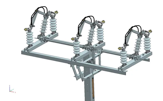
Center Break Isolator and double Break Isolator
Preview
Preview
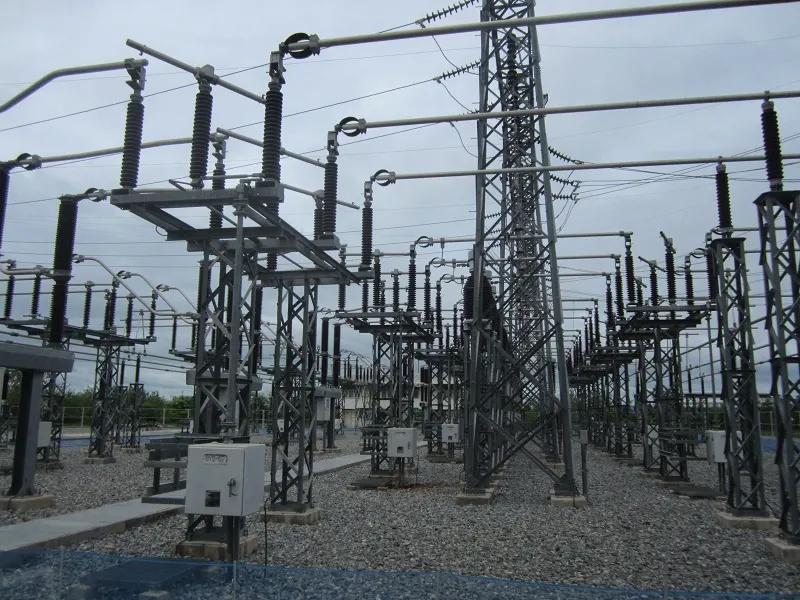
These disconnectors are , no load switching devices
which physically isolate the lines. They are designed for
horizontal outdoor application and can also be designed
for vertical installation. For earthing and closing of
switchyard portions of the installation, the earthing
switches are provided on disconnector. If required.
The following documents were referred to during the preparation of this specification. In case of conflict, the provisions of this specification shall take precedence.
IEC 129:1975: Alternating Current Disconnectors (Isolators) and Earthing Switches
IEC 60694:2002: Common Specifications for High Voltage Switchgear and Controlgear
BS 729: Hot dip galvanized coating on iron and steel articles
IEC62271-102
Isolator (Disconnector) - a mechanical switching device which provides, in the open position, an isolating distance in accordance with Electrical Safety requirements.
SERVICE CONDITIONS
The isolator shall be suitable for continuous operation outdoors in tropical areas at altitudes of up to 2200m above sea level, humidities of up to 90%, average ambient temperature of +30ºC with a minimum of -1ºC and a maximum of +40ºC and heavy saline conditions along the coast.
4.2. DESIGN AND CONSTRUCTION
4.2.1 The Isolator, Solid Link shall be designed and constructed in accordance with IEC 129 and IEC 60694.
4.2.2 The isolating link shall be of the vertical opening, designed for single phase manual operation. It shall be easily removed and replaced by using a portable operating rod.
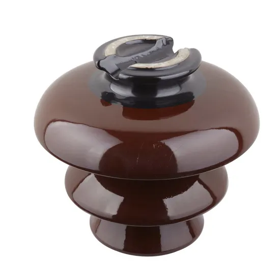
4.2.3 The isolating link shall incorporate double porcelain insulators to suit voltage requirements and mounted on hot dipped galvanised steel under base suitable for vertical mounting.
4.2.4 The isolating link shall be arranged so that each unit is mounted independently on an angle bracket. It shall be supplied complete with the angle bracket and accessories suitable for mounting on 'U' type steel channel. The drawings to be submitted shall indicate all the applicable mounting positions.
4.2.5 The isolator shall be designed such that in fully open position, it shall provide adequate electrical isolation between the contacts on each phase. It shall conform to the requirement as single point isolation for safety.
4.2.6 All steel parts shall be hot dip galvanized to BS 729. The minimum coating of galvanizing required is 80 microns.
4.2.7 The solid link shall be removable from the mounting by use of operating rod.
4.2.8 All current carrying parts of the isolator shall be made of high conductivity material.
4.2.9 The isolator shall be fitted with clamp connectors for Aluminium (ACSR) conductor of
Aluminium (ACSR)conductor of up to 18.2mm diameter.
The rating of the complete isolator shall be as follows: -
Rated voltage
36 kV
Rated frequency
50 Hz
Rated lightning impulse withstand voltage
200 kV
Rated power frequency withstand voltage, dry
95 kV
Rated normal current
400 Amps
Rated short time withstand current for 3 sec, min.
18.0 kA
Minimum creepage distance of insulators
900 mm
SOLID LINKS 11KV
TRI-LINKS
Lot 3-(a) 11kV with interrupters
FURTHER REQUIREMENTS:
Water shall not be able to accumulate on any part of the equipment nor shall any feature introduce moisture into any component.The design shall incorporate all reasonable precautions and provisions for the safety of personnel concerned with the operation and maintenance of the same.The current path shall be such that load current shall only flow through high conductive materials such as copper and its alloys. Load current shall not be permitted to flow through ferrous components, springs, or spring-loaded mechanisms.All load current paths shall be so designed that the relevant parts of the switch are capable of carrying the specified rated current without exceeding the permitted temperature rise.SUPPLIMENTARY NOTES
Suppliers should give sufficient information including drawings (which must be brief, clear and to the point) on how their switch designs addresses these requirements. Further, Suppliers may offer better alternatives that are of cost benefits to customer, It is therefore imperative that schedule "B" is completed by the tenderer. Any deviations/modifications/alternatives specification must be listed in schedule "C.
33kV with interrupters
FURTHER REQUIREMENTS:
Water shall not be able to accumulate on any part of the equipment nor shall any feature introduce moisture into any component.The design shall incorporate all reasonable precautions and provisions for the safety of personnel concerned with the operation and maintenance of the same.The current path shall be such that load current shall only flow through high conductive materials such as copper and its alloys. Load current shall not be permitted to flow through ferrous components, springs, or spring-loaded mechanisms.All load current paths shall be so designed that the relevant parts of the switch are capable of carrying the specified rated current without exceeding the permitted temperature rise.SUPPLIMENTARY NOTES
Suppliers should give sufficient information including drawings (which must be brief, clear and to the point) on how their switch designs addresses these requirements. Further, Suppliers may offer better alternatives that are of cost benefits to custoemr.
11kV without interrupters
FURTHER REQUIREMENTS:
Water shall not be able to accumulate on any part of the equipment nor shall any feature introduce moisture into any component.The design shall incorporate all reasonable precautions and provisions for the safety of personnel concerned with the operation and maintenance of the same.The current path shall be such that load current shall only flow through high conductive materials such as copper and its alloys. Load current shall not be permitted to flow through ferrous components, springs, or spring-loaded mechanisms.All load current paths shall be so designed that the relevant parts of the switch are capable of carrying the specified rated current without exceeding the permitted temperature rise.SUPPLIMENTARY NOTES
Suppliers should give sufficient information including drawings (which must be brief, clear and to the point) on how their switch designs addresses these requirements. Further, Suppliers may offer better alternatives that are of cost benefits to
33kV without interrupters
FURTHER REQUIREMENTS
:
W
a
ter sh
ll not be
ble
t
o
acc
umu
l
te on
n
y p
rt of the
e
quip
m
nt nor sh
ll
y
f
ea
tu
r
e in
rodu
c
e mo
i
sture in
ompo
nt.
The d
sign
s
h
ll inco
po
te
ll re
son
ble p
ut
ons
nd p
ovis
ons for the s
y of p
rsonn
l co
ce
d with
he op
on
nd main
e of the s
.
The
ur
nt path sh
ll be su
h that load
nt sh
ll on
y flow through high
ondu
ve mat
ri
ls
u
opp
nd i
s.
L
d
re
nt shall not be p
rmit
d to flow through f
ous
omponents, spr
ngs, or sp
in
g
-
load
d m
nis
All
nt
p
ths
ll be so d
signed th
e r
le
v
nt pa
ts of the s
w
ca
ing
he s
ec
ifi
d r
nt wi
hout ex
ee
ding
he p
d temp
ture ri
S
UPPLIMENTARY NOTES
uppl
rs should give su
fi
ient info
mation
ding dr
wings (
hich
ust be b
ie
,
nd to
he poin
) on
ow th
ir switch d
signs
dd
sses th
se
quir
ments.
F
urth
r, Supplie
s m
y o
b
rn
s that
ost be
s to.
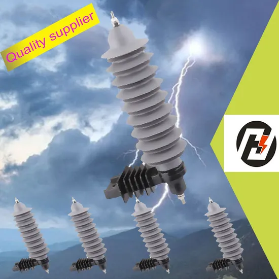
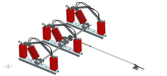
load-break disconnector switches
are designed for low-load breaking
overhead MV electrical lines. Equipped
with an air-break technology system
combined with an isolating switch in
series, this device provides visible opening
and great safety in operation.switches are suitable for overhead
distribution networks up to 36 kV, and
especially those requiring a high level of
insulation: • No maintenance required •
Easy pole top mounting • Line works can
be carried in safe conditions thanks to the
visible opening and high level of
insulation • A manual control mechanism
is available with a rod assembly and
padlockable lever • Whip breaking system
• The ISAR-A switch control mechanisms
are equipped with a tumbler spring
system which directly operates the mobile
shaft. The operating speed is not
dependent on the operator • Height of the
pole from 11 to 14 m • Porcelain
insulators as per standard CEI 60273
Technical Characteristics Rated voltage: 24
kV / 36 kV Rated current: 200 A / 400 A
Breaking capacity: 80 A Rated peak closing
capacity: 25 kA This equipment is fully
compliant with international standard (IEC
62271-103).
which physically isolate the lines. They are designed for
horizontal outdoor application and can also be designed
for vertical installation. For earthing and closing of
switchyard portions of the installation, the earthing
switches are provided on disconnector. If required.
The following documents were referred to during the preparation of this specification. In case of conflict, the provisions of this specification shall take precedence.
IEC 129:1975: Alternating Current Disconnectors (Isolators) and Earthing Switches
IEC 60694:2002: Common Specifications for High Voltage Switchgear and Controlgear
BS 729: Hot dip galvanized coating on iron and steel articles
IEC62271-102
Isolator (Disconnector) - a mechanical switching device which provides, in the open position, an isolating distance in accordance with Electrical Safety requirements.
SERVICE CONDITIONS
The isolator shall be suitable for continuous operation outdoors in tropical areas at altitudes of up to 2200m above sea level, humidities of up to 90%, average ambient temperature of +30ºC with a minimum of -1ºC and a maximum of +40ºC and heavy saline conditions along the coast.
4.2. DESIGN AND CONSTRUCTION
4.2.1 The Isolator, Solid Link shall be designed and constructed in accordance with IEC 129 and IEC 60694.
4.2.2 The isolating link shall be of the vertical opening, designed for single phase manual operation. It shall be easily removed and replaced by using a portable operating rod.
4.2.3 The isolating link shall incorporate double porcelain insulators to suit voltage requirements and mounted on hot dipped galvanised steel under base suitable for vertical mounting.
4.2.4 The isolating link shall be arranged so that each unit is mounted independently on an angle bracket. It shall be supplied complete with the angle bracket and accessories suitable for mounting on 'U' type steel channel. The drawings to be submitted shall indicate all the applicable mounting positions.
4.2.5 The isolator shall be designed such that in fully open position, it shall provide adequate electrical isolation between the contacts on each phase. It shall conform to the requirement as single point isolation for safety.
4.2.6 All steel parts shall be hot dip galvanized to BS 729. The minimum coating of galvanizing required is 80 microns.
4.2.7 The solid link shall be removable from the mounting by use of operating rod.
4.2.8 All current carrying parts of the isolator shall be made of high conductivity material.
4.2.9 The isolator shall be fitted with clamp connectors for Aluminium (ACSR) conductor of
Aluminium (ACSR)conductor of up to 18.2mm diameter.
The rating of the complete isolator shall be as follows: -
Rated voltage
36 kV
Rated frequency
50 Hz
Rated lightning impulse withstand voltage
200 kV
Rated power frequency withstand voltage, dry
95 kV
Rated normal current
400 Amps
Rated short time withstand current for 3 sec, min.
18.0 kA
Minimum creepage distance of insulators
900 mm
SOLID LINKS 11KV
TRI-LINKS
Lot 3-(a) 11kV with interrupters
FURTHER REQUIREMENTS:
Water shall not be able to accumulate on any part of the equipment nor shall any feature introduce moisture into any component.The design shall incorporate all reasonable precautions and provisions for the safety of personnel concerned with the operation and maintenance of the same.The current path shall be such that load current shall only flow through high conductive materials such as copper and its alloys. Load current shall not be permitted to flow through ferrous components, springs, or spring-loaded mechanisms.All load current paths shall be so designed that the relevant parts of the switch are capable of carrying the specified rated current without exceeding the permitted temperature rise.SUPPLIMENTARY NOTES
Suppliers should give sufficient information including drawings (which must be brief, clear and to the point) on how their switch designs addresses these requirements. Further, Suppliers may offer better alternatives that are of cost benefits to customer, It is therefore imperative that schedule "B" is completed by the tenderer. Any deviations/modifications/alternatives specification must be listed in schedule "C.
33kV with interrupters
FURTHER REQUIREMENTS:
Water shall not be able to accumulate on any part of the equipment nor shall any feature introduce moisture into any component.The design shall incorporate all reasonable precautions and provisions for the safety of personnel concerned with the operation and maintenance of the same.The current path shall be such that load current shall only flow through high conductive materials such as copper and its alloys. Load current shall not be permitted to flow through ferrous components, springs, or spring-loaded mechanisms.All load current paths shall be so designed that the relevant parts of the switch are capable of carrying the specified rated current without exceeding the permitted temperature rise.SUPPLIMENTARY NOTES
Suppliers should give sufficient information including drawings (which must be brief, clear and to the point) on how their switch designs addresses these requirements. Further, Suppliers may offer better alternatives that are of cost benefits to custoemr.
11kV without interrupters
FURTHER REQUIREMENTS:
Water shall not be able to accumulate on any part of the equipment nor shall any feature introduce moisture into any component.The design shall incorporate all reasonable precautions and provisions for the safety of personnel concerned with the operation and maintenance of the same.The current path shall be such that load current shall only flow through high conductive materials such as copper and its alloys. Load current shall not be permitted to flow through ferrous components, springs, or spring-loaded mechanisms.All load current paths shall be so designed that the relevant parts of the switch are capable of carrying the specified rated current without exceeding the permitted temperature rise.SUPPLIMENTARY NOTES
Suppliers should give sufficient information including drawings (which must be brief, clear and to the point) on how their switch designs addresses these requirements. Further, Suppliers may offer better alternatives that are of cost benefits to
33kV without interrupters
FURTHER REQUIREMENTS
:
W
a
ter sh
ll not be
ble
t
o
acc
umu
l
te on
n
y p
rt of the
e
quip
m
nt nor sh
ll
y
f
ea
tu
r
e in
rodu
c
e mo
i
sture in
ompo
nt.
The d
sign
s
h
ll inco
po
te
ll re
son
ble p
ut
ons
nd p
ovis
ons for the s
y of p
rsonn
l co
ce
d with
he op
on
nd main
e of the s
.
The
ur
nt path sh
ll be su
h that load
nt sh
ll on
y flow through high
ondu
ve mat
ri
ls
u
opp
nd i
s.
L
d
re
nt shall not be p
rmit
d to flow through f
ous
omponents, spr
ngs, or sp
in
g
-
load
d m
nis
All
nt
p
ths
ll be so d
signed th
e r
le
v
nt pa
ts of the s
w
ca
ing
he s
ec
ifi
d r
nt wi
hout ex
ee
ding
he p
d temp
ture ri
S
UPPLIMENTARY NOTES
uppl
rs should give su
fi
ient info
mation
ding dr
wings (
hich
ust be b
ie
,
nd to
he poin
) on
ow th
ir switch d
signs
dd
sses th
se
quir
ments.
F
urth
r, Supplie
s m
y o
b
rn
s that
ost be
s to.
load-break disconnector switches
are designed for low-load breaking
overhead MV electrical lines. Equipped
with an air-break technology system
combined with an isolating switch in
series, this device provides visible opening
and great safety in operation.switches are suitable for overhead
distribution networks up to 36 kV, and
especially those requiring a high level of
insulation: • No maintenance required •
Easy pole top mounting • Line works can
be carried in safe conditions thanks to the
visible opening and high level of
insulation • A manual control mechanism
is available with a rod assembly and
padlockable lever • Whip breaking system
• The ISAR-A switch control mechanisms
are equipped with a tumbler spring
system which directly operates the mobile
shaft. The operating speed is not
dependent on the operator • Height of the
pole from 11 to 14 m • Porcelain
insulators as per standard CEI 60273
Technical Characteristics Rated voltage: 24
kV / 36 kV Rated current: 200 A / 400 A
Breaking capacity: 80 A Rated peak closing
capacity: 25 kA This equipment is fully
compliant with international standard (IEC
62271-103).
Preview
证书
标题:ASTA test report expulsion fuse

Preview


 上海
上海  已认证
已认证