Product
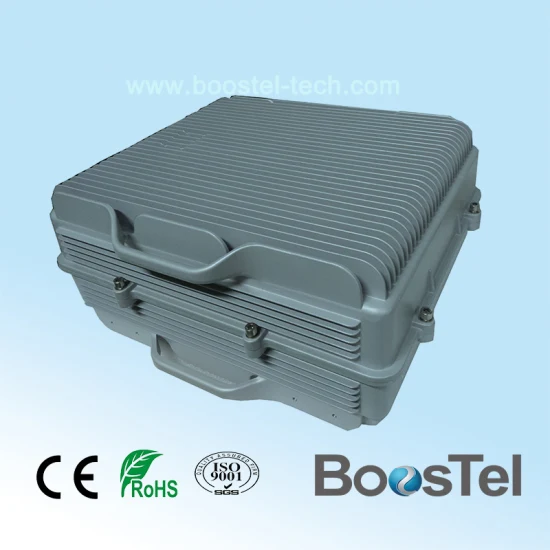

Preview
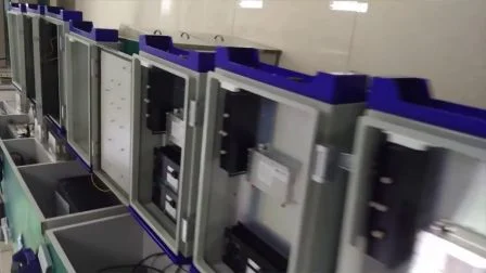
Basic Info.Product DescriptionCertifications
Basic Info.
| Model NO. | BT-BA43D |
| Lightning Protection | Lightning Arrester |
| Certification | ISO |
| Condition | New |
| Transport Package | Wooden Case |
| Specification | 560*450*270mm |
| Trademark | BOOSTEL |
| Origin | China |
| Production Capacity | 2000 Set/Year |
Product Description
Product Description
Preview
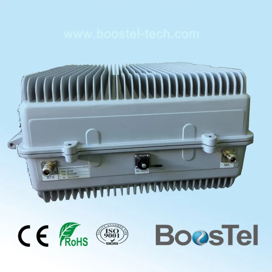
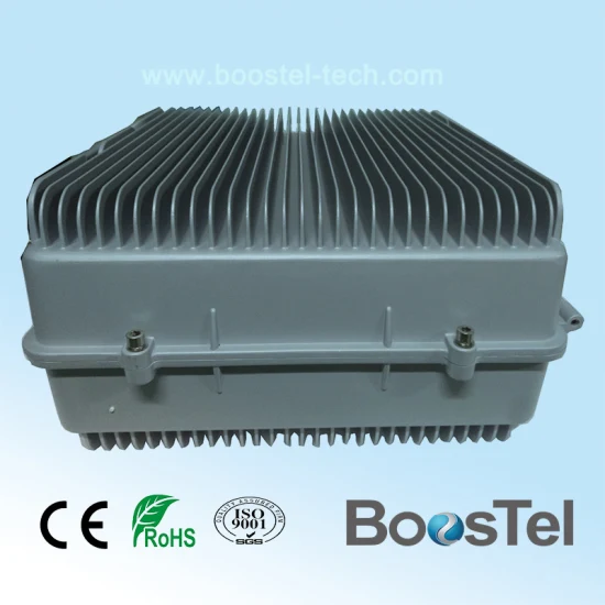
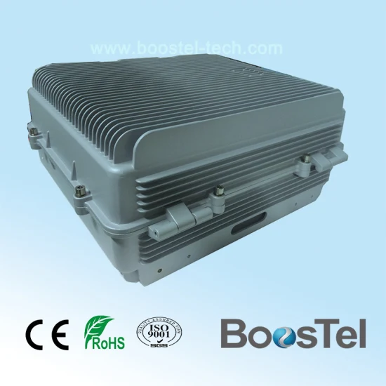
Specifications of Digital TV RF Repeater
Model: BT-BA43D
The Digital TV RF Repeater (RFR) is designed to provide a more cost-effective solution than adding a new digital TV transmitter to improve network coverage and signal quality of digital TV. And its easy installation and maintenance can help carrier get fast return.
The repeater is working as a relay between the TV transmitter and receivers during the broadcasting of digital TV signal. It receives low-power TV signal from the TV transmitter via the Donor Antenna, linearly amplifies the signal and then retransmits it via the Coverage Antenna to the weak/blind coverage area.
The enhancer can amplify the signal within the customized band.
Aluminum-alloy casing with IP65 protection has high resistance to dust, water and corrodingNo interference to BTS by adopting linear amplifier with high gain and low noiseAdopting filter with highly selectivity and low insertion loss eliminates interference between uplink and downlinkUSB port provides a link to a notebook for local supervision or to the built-in wireless modem to communicate with the NMS (Network Management System) that can remotely supervise repeater's working status and download operational parameters to the repeater
Applications
To expand signal coverage or fill signal blind area where
signal is weak or unavailable.
Technical Specifications
Preview
Preview

Preview
Preview
Preview
Installation & Commissioning
1.1 Installation
1.1.1 Steps for mounting on the Pole
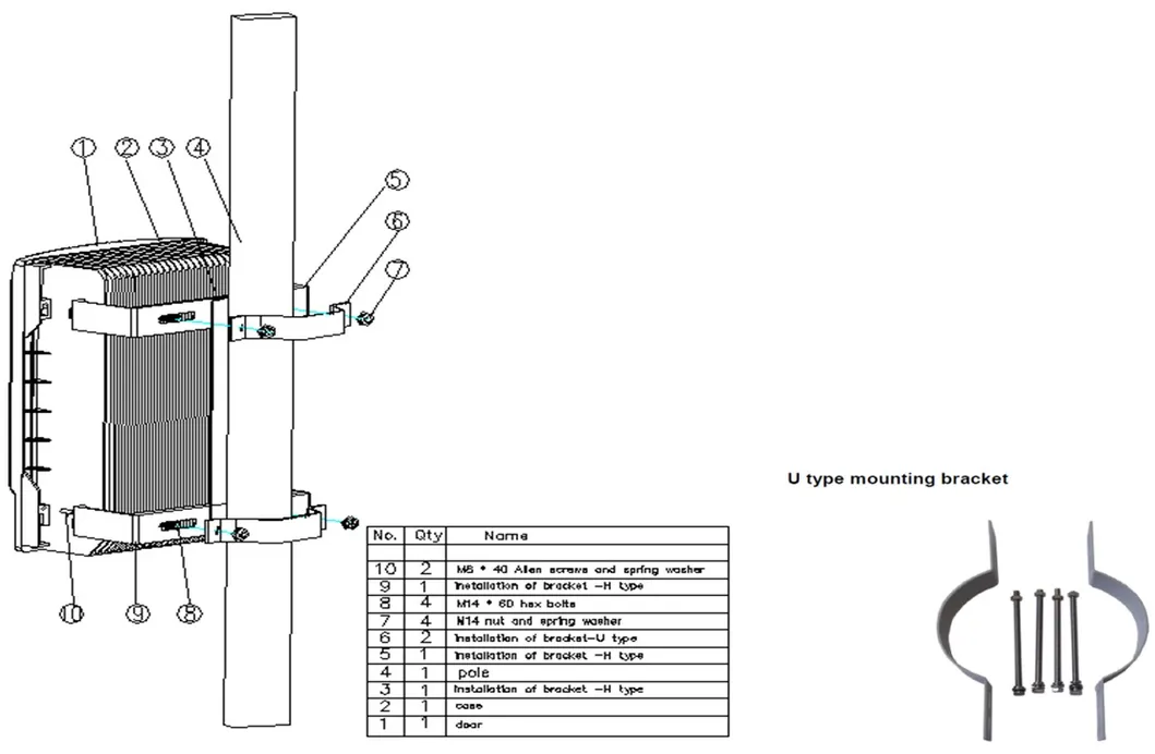
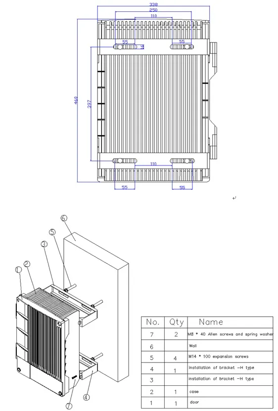
At Donor site, install the FSR Donor Unit, Donor Antenna, Link Antenna, and RF cable as per specified plan and site layout. FSR Donor Unit can be pole-mounted using the brackets as shown below.Place M8 screws through the holes of H type brackets as shown in figure 1
Fix combiner onto the H type brackets with M6 screws
Fix H type brackets with combiner installed onto the pole with U type brackets and M8 screws
Figure 1 Repeater Mounting Bracket
Orient the Link Antenna of Donor Site to the direction of the Remote Site.Use Site Master to measure the VSWR of the RF cable from the Link Antenna. The value should be less than 1.5; Otherwise, check the connectors and the installation of the cable.Start Commissioning the Donor Unit .Proceed to the Remote Site.At Remote site, install the FSR Remote Unit, Link Antenna, Coverage Antenna, and RF cables. Remote Unit can be wall mounted or pole mounted depending on the approved plan.Orient the Remote Link Antenna to the direction of the Donor Site.Using Spectrum Analyzer, check the Link RSL; adjust the Link Antennas of both Donor and Remote until the required RSL is achieved. Link RSL can be computed using conventional path calculation method.Then, measure the VSWR of the RF cables connecting with the Link Antenna of Remote Unit. The value should be less than 1.5, otherwise, check the connectors and the installation of the cable.Start Commissioning the Remote Unit .1.1.2 Steps for mounting on the wall
At Donor site, install the FSR Donor Unit, Donor Antenna, Link Antenna, and RF cable as per specified plan and site layout. FSR Donor Unit can be wall-mounted using the brackets as shown below.Make four marks on the wall according to the dimension shown as figure 2
Drill four holes at position marked
Fix two pcs H type brackets on the wall with M8 expansion screws
Fix combiner onto the brackets with M6 screws
Figure 2 Repeater Mounting Bracket
6. The following steps are the same with step 4 to 12 for mounting on the Pole.1.2 Commissioning
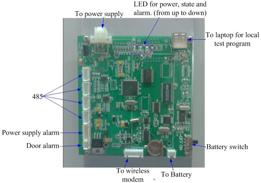
Connect the RF cable from Donor Antenna to the spectrum analyzer and check if the Donor Antenna is receiving the correct frequency; and then measure the signal level of the said frequency (RSL). Adjust the antenna to make the readings approach the recorded value on the survey report. Record all readings.Inside the repeater, disconnect the uplink duplexer to the ICS module so as to cut any signal coming from air going to the uplink duplexer and thus protecting the amplifier from damaging. Connect a 30 dB attenuator to the output of the repeater; this attenuator will serve as a load for the repeater. The purpose of this attenuator is to protect the equipments from damaging.Turn ON the repeater. Observe the LED display on the NMS board. Check for any alarm. Under normal condition, the POWER LED should be always green and the RUN LED should be blinking, the ALARM LED should be not bright with red color.Figure3
Interface of NMS Board
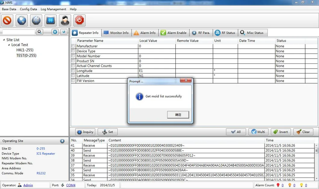
Connect your laptop to the repeater via the data cable.
1.1 Installation
1.1.1 Steps for mounting on the Pole
At Donor site, install the FSR Donor Unit, Donor Antenna, Link Antenna, and RF cable as per specified plan and site layout. FSR Donor Unit can be pole-mounted using the brackets as shown below.Place M8 screws through the holes of H type brackets as shown in figure 1
Fix combiner onto the H type brackets with M6 screws
Fix H type brackets with combiner installed onto the pole with U type brackets and M8 screws
Figure 1 Repeater Mounting Bracket
Orient the Link Antenna of Donor Site to the direction of the Remote Site.Use Site Master to measure the VSWR of the RF cable from the Link Antenna. The value should be less than 1.5; Otherwise, check the connectors and the installation of the cable.Start Commissioning the Donor Unit .Proceed to the Remote Site.At Remote site, install the FSR Remote Unit, Link Antenna, Coverage Antenna, and RF cables. Remote Unit can be wall mounted or pole mounted depending on the approved plan.Orient the Remote Link Antenna to the direction of the Donor Site.Using Spectrum Analyzer, check the Link RSL; adjust the Link Antennas of both Donor and Remote until the required RSL is achieved. Link RSL can be computed using conventional path calculation method.Then, measure the VSWR of the RF cables connecting with the Link Antenna of Remote Unit. The value should be less than 1.5, otherwise, check the connectors and the installation of the cable.Start Commissioning the Remote Unit .1.1.2 Steps for mounting on the wall
At Donor site, install the FSR Donor Unit, Donor Antenna, Link Antenna, and RF cable as per specified plan and site layout. FSR Donor Unit can be wall-mounted using the brackets as shown below.Make four marks on the wall according to the dimension shown as figure 2
Drill four holes at position marked
Fix two pcs H type brackets on the wall with M8 expansion screws
Fix combiner onto the brackets with M6 screws
Figure 2 Repeater Mounting Bracket
6. The following steps are the same with step 4 to 12 for mounting on the Pole.1.2 Commissioning
Connect the RF cable from Donor Antenna to the spectrum analyzer and check if the Donor Antenna is receiving the correct frequency; and then measure the signal level of the said frequency (RSL). Adjust the antenna to make the readings approach the recorded value on the survey report. Record all readings.Inside the repeater, disconnect the uplink duplexer to the ICS module so as to cut any signal coming from air going to the uplink duplexer and thus protecting the amplifier from damaging. Connect a 30 dB attenuator to the output of the repeater; this attenuator will serve as a load for the repeater. The purpose of this attenuator is to protect the equipments from damaging.Turn ON the repeater. Observe the LED display on the NMS board. Check for any alarm. Under normal condition, the POWER LED should be always green and the RUN LED should be blinking, the ALARM LED should be not bright with red color.Figure3
Interface of NMS Board
Connect your laptop to the repeater via the data cable.
Preview

Preview
Preview

Preview

Preview
Certifications
Name:CE of Pico Repeater

Preview
UHF 100MHz 400MHz 800MHz Digital TV Cellular Repeater
$20 ~ $49.86
Consumer electronics Industry Chain · Telecommunications and broadcasting · Repeater
Model NO.:BT-BA43D
Transport Package:Wooden Case
Origin:China


 Shenzhen
  Authenticated
Less than 50 EmployeesElectronics/Semiconductor/Integrated Circuit
Top Products from the Supplier


Negotiation